This dendrometer is using rotary potentiometer for tree trunk displacement detection. Rotary potentiometer is for measuring the electromotive which forced by balancing it against the potential difference produced by current through variable resistance. Depending on Expansion and contraction of wire, pully will rotate and rotated angle will be shown as changed resistance value. The resistance value will not be able to read by dendrometer; thus, resistance value will be replaced with voltage. This page will explain how we set the cable which allow replacing resistance value with voltage.
Picture 1. MIJ-02 Wiring Diagram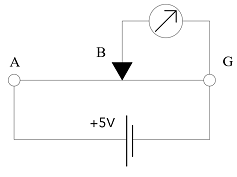
See picture 1.
A to G shows total resistance of potentiometer, and B to G shows variable resistance depend on displacement. This mean B move between A and G. In general, measurement range of dendrometer is 5V. For instance, applying 5V preheat to A to G, then the voltage change between B and G will be change 0 – 5V the depending on how much wire displaced.
Another example using MIJ-02; When B move to A which will be5V or if B stays at G the voltage will be 0V.
If preheat changed 5V to 2V, displace met will show between 0 to 2V. Thus the output voltage will be changed depending on preheat voltage this is called ratiometric.
Normally, potentio and resistance have temperature characteristic that as temperature changed value will also change; thus, temperature characteristic will be issue for instruments used for field observations. However, if the instruments have unchanged preheat ratiometric system then output has no temperature dependence so we do not need to care about temperature characteristic influence on instruments.
*There is warning or preheat setting that if applied 12V which may cause logger damage; this is because the maximum output is 12V.
Supplement:
Voltage measurement between B and G will be larger as tree trunk enlarges so the value is proportional relationship. On the other side between A and B is inverse relationship that as the enlarge the voltage will become smaller.
Below table shows MIJ-02 pinassign
| cable color | Role | MIJ01 Logger | Meanig fo Pic 1 |
| Red | Preheat+ | Preheat + | A |
| Black | Preheat GND | Preheat G | G |
| White | Voltage output + | SE-1 | B |
Please use the equation that convert voltage to displacement
dL(um)=29059.7(um)×Vout(V)/Vpre(V)
dL: displacement um
Vout: voltage output
Vpre: preheat voltage
For MIJ-01: Jut input 29059.7*X001/5000 into PVS.
When using MIJ-01 data logger please use below link
(setup file and download the cabling diagram )
http://www.environment.co.jp/product/Logger/WiringandSetting.html